| |
Build a Butterfly - Carrara
Tutorial
By Carl
E.Schou
|
Monarch of
the Morning |
|
|
For this month's foray into
the Digital Domain, we are going to model a Monarch
Butterfly in Carrara Studio 2. Our goal here is to
build a fairly simple butterfly model that has enough
details to pass muster, yet be small enough in file size
to be practical for use in a crowd
scene. |
|
|
Background
on the Monarch Butterfly
The Monarch butterfly is
also known as the milkweed butterfly, after the plant
that makes up the butterfly's diet during the larval
stage. As an adult, the Monarch subsists on
nectar. The milkweed diet gives the butterfly a
bitter taste that is its best protection against
predators. Birds associate the Monarch's color
with its toxicity and learn to avoid eating them.
Other species mimic the color of the Monarch to take
advantage of this. Huge migrations take place
every year as the Monarchs travel to their
over-wintering sites in Mexico, Florida, California, and
coastal Texas. Some tagged Monarchs have been
known to travel 1200 miles in these migrations.
The wingspan of the Monarch is about three to four
inches and the Latin name is Danaus
plexippus. |
|
|
Strategy
for Modeling a Monarch
There are three phases to
this project. The first phase involves the
generation of the image maps for the wings. The
second phase involves the generation of the model.
The third phase involves the application of the image
maps and textures to the model.
For the first phase, we are
going to start by generating the image and alpha maps
that will be used for the wings, using Photoshop or
the2D paint program of your choice. The dimensions
of the wing maps will be needed for the modeling phase
of the project.
For the second phase, we
will begin modeling by entering Carrara's Vector
modeler, drawing an outline of the body and lathing it
to produce the 3D solid . We'll add a pair of
spheres for the eyes. We'll also add a simple set
of legs, a pair of antennae, and a proboscis using the
Spline modeler. For the wings, we'll add two pairs
of rectangles for the front and rear, left and right
wings.
For the third phase, we
will add the image maps of butterfly wings and matching
alpha maps to make the non-wing parts of the rectangle
transparent. We will also add a simple image map
for the body of the
butterfly. |
|
|
Make the
Image Maps
The image maps for the
wings can be produced by scanning a drawing or a
photograph. You can also paint your own in a 2D
painting program. For this project, I photographed
a mounted specimen of a Monarch butterfly that I
purchased for this project through eBay. The top
and bottom views of this Monarch are shown
below. |
|
|
Looking at the two images above, a couple of
points are apparent which will have an impact on how we
model the wings. First, the wings are darker on
top than underneath. Second, we only have a
complete view of the upper pair of wings in the top
view. Similarly, we only have a complete view of
the lower pair of wings in the bottom view. Third,
the wings could not be laid completely flat when taking
the two photographs, so the shape of a given wing is
going to be slightly different between the top and
bottom views.
To work around these
problems, we are going to do our mapping using the
images from just two of the wings. We will use the
top view of one of the upper wings for the top and
bottom image maps for that wing. To produce the
underside of the upper wing, we will adjust the
brightness and contrast to get the color right. We
will do the same with the top view of the lower wing,
adjusting the brightness and contrast to produce the
image for the bottom side of the lower wing. This
will give us image maps for the top and bottom faces of
the two wings on one side of the body. Later on,
the wings on the other side of the body will be produced
by mirroring the mapped rectangle wing
objects.
The image below shows the
color and alpha maps made in Photoshop from the top view
of the upper left wing. To produce the bottom
view color image of this wing, adjust the
brightness and contrast to get the right look for the
underside and save the image under a new name.
Note that the same alpha map is used for top and bottom
surface of the
wing. |
|
|
The
same process was used to produce the color and alpha
maps for the top view of the lower right wing, shown
below. Note that the top edge of this wing's image
was cloned from the underside image since this portion
of the lower wing is hidden by the upper wing.
Produce the bottom view image of this wing by adjusting
the brightness and contrast to get the right look for
the underside. |
|
|
Build the
Body
In the Carrara Assembly
room, drag the Vertex Object icon into the 3D View to
insert a Vertex object. This will put you into the
Vertex modeling room. Select the Polyline tool and
build the outline shown in the Left View Window
below. Make sure the end points of the outline are
resting on the Y axis so that X =
0. |
|
|
Next
we Lathe the outline to produce the 3D object.
Make sure all of the points are selected and press
Construct>Lathe and press Enter. Select
everything and turn on Subdivision Surfaces in the
Properties tray at the right side of the screen.
Your view should look similar to the image below.
Return to the Assembly room and use the Properties tray
to change the name of this part to
Body. |
|
|
Add the
Eyes
Once again, drag the Vertex
Object icon into the 3D View to insert a Vertex
object. In the Vertex modeling room, click
Insert>Sphere and accept the default model with 60
facets. Return to the Assembly room and set the
overall size to 15%. Set the X size to 50% and the
Z size to 150%. Move it to the right side of the
head and use the Properties tray to change the name of
this part to Eye Right. Then use the Duplicate
With Symmetry function in the Edit menu to mirror the
eye around the plane of the X axis. Rename the new
eye as EyeLeft.
The top and side view
images below show the placement of the eyes in the
Assembly room. These images will also be used as
reference in the following sections for the adding of
the antennae and
legs. |
|
|
Build the
Antennae and Legs
Still in the Assemble room,
drag the Spline Object icon into the 3D View to insert
that object and enter the Spline modeling room, then
click Geometry>ExtrusionMethod>Translation.
Also under Geometry, click Envelope>None.
Create a line with five control points adjusted as shown
below. The ConvertPoint tool was used to allow the
path to curve smoothly as it passed through the three
middle points. Return to the Assembly room and
name this object to
AntennaLeft. |
|
|
Create another Spline object. In the Spline
modeler's Geometry menu, choose Pipeline for the
Extrusion Method. Also under Geometry, select a
Symmetrical Envelope. Create a line with six
control points adjusted as shown below. In the
Left view, the purple line is the extrusion path and the
blue lines are the extrusion envelope. Notice that
the ConvertPoint tool was not used since we want the
legs to be built from individual straight sections
without curves. Return to the Assembly room and
name this object to
LegLeft1. |
|
|
Now
we are going to scale, duplicate and mirror the antennae
and the legs. Back in the Assemble room, select
the AntennaLeft object and scale the overall size to
80%. Set Yaw to -165, Pitch to -90, and Roll to
-165. Move the antenna into the position shown in
the Top view image illustrating the placement of the
eyes. You may need to tweak the scale or rotations
to account for differences in the models. When you
are satisfied with the left antenna, click
Edit>DuplicateWithSymmetry and mirror the object
about the X axis. When you are done, rename this
new object AntennaRight.
To produce the legs, select
the object LegLeft1, and Duplicate it twice, renaming
the duplicates as LegLeft2 and LegLeft3. Set the
Pitch on LegLeft1 to 15, the Roll to 30, and the overall
size to 25%. For LegLeft2, set Yaw to 90, Pitch
and Roll to 0, and overall size to 55%. For
LegLeft3, set Yaw to 120, Pitch and Roll to 0, and
overall size to 55%. Arrange the legs as shown in
the Top and Side view image illustrating the placement
of the eyes. LeftLeg1 is in front, LeftLeg2 is in
the middle, and LeftLeg3 is in the rear. Select
LegLeft1 and Duplicate with Symmetry around the X
axis. Rename the new object as LegRight1.
Repeat this process on LegLeft2 and 3 to produce
LegRight2 and 3. |
|
|
Add the
Proboscis
To allow our butterfly to
feed, we are going to have to give it a proboscis.
This is the tongue-like tube used for sipping nectar
from flowers. Construct this object in the Spline
modeler by extruding a circular cross section on a
spiral shaped path as shown below. The path was
made up of ten points, with each point's handles
adjusted to produce a smooth spiral. Be sure to
use the pipeline extrusion method. Back in the
Assembly room, rename this object Proboscis, scale it
and move it to the proper size and
position. |
|
|
Export the
Butterfly for Mapping
Now we are going to apply
UV Mapping to the butterfly's body so we can apply a
simple texture map to it. The way we export it for
mapping will depend on whether we are using Subdivision
Surfaces, and how we are going to use the model
afterwards. If we are going to do our rendering in
Carrara, then we only need to export the groups needing
mapping as an OBJ file, apply UV Mapping to it, then
import the mapped model back into Carrara for texturing
and rendering. The same approach is used if
Subdivision Surfaces were not used.
With Subdivision Surfaces,
exporting a model becomes a little more involved.
This is because Subdivision Surfaces are calculated at
render time in Carrara so when you export your model,
you only export the basic wireframe used to control the
Subdivision Surfaces. If the model is going to be
used in applications that do not support Subdivision
Surfaces and you don't want to lose this feature, then
it will be necessary to convert the Subdivision Surfaces
to an actual mesh. This is done by selecting only
the model groups that are Subdivided, click on Edit,
then ConvertToOtherModeler, and convert the mesh to the
Primitive Modeler. Repeat, but this time convert
the mesh to the Vertex Modeler. This mesh is then
exported as an OBJ file for UV
mapping. |
|
|
Apply the
UV Mapping
Import the OBJ file into
UVMapper and apply UV coordinates to the model by
clicking Map>Planar. On the pop-up window that
opens, set alignment to the X axis and select Don't
Split. You should see something similar to the
image below. Note that this image has been rotated
90 degrees CCW to better fit the page. Save the
mapped model as a new OBJ file and save the template
image. Import the template to Photoshop, add a new
layer, and paint a few black dots along the tail end
chest region. Fill the layer underneath with
white, flatten the image, invert the colors and save as
your BodyImage map. Back in Carrara, clear the
scene and load the new mapped OBJ file back in.
Select the body, go into the Texture room, and apply the
texture you just created using parametric
mapping. |
|
|
Build the
Wings
To build the wings, we start by dragging the
Vertex Object icon into the 3D View to insert a Vertex
object. In the Vertex modeling room, click
Insert>Rectangle. For the U size ad V size, use
numbers with the same ratio as the pixel dimensions for
your wing image maps. For example, the images I
used were 717 by 922 pixels, so I set U to 7.17 and V to
9.22. Back in the Assembly room, adjust the
overall scale to get the rectangle about twice the
length of the body and move it into the approximate
position for the left wing. Some starting values
would be 500% for the overall size. For the
position, try -17 for X, 3 for Y, and 5 for the Z.
The exact values will vary from model to model and you
will need to do test renders of the fully textured model
later on to get the wing size and position exactly
right. Rename the rectangle to UpperLeftWing, then
duplicate it and rename the duplicate
LowerLeftWing. Lower the Z position of the
LowerLeftWing by 0.1 so that it is just a little lower
than the upper wing. Now group the two wing pieces
together and call the group WingsLeft. Move the
Hotpoint to the place where the wing attaches to the
body so that the wing will flap
correctly. |
|
|
Apply the
Wing Textures
To apply the wing textures,
we are going to use two shader layers. The first shader layer will be applied to the top of
the wing and the second shader layer will be applied to
the bottom. A flat mapped, multi-channel set up will be
used. The color channel is set to contain two
sources where the alpha map (source 2) is subtracted from the
top color map (source 1). The alpha map is also
loaded into the transparency channel. All the
other channels should be given a Value of 0%. Just
saying “None” for the unused channels is not
enough.
The first layer which was applied to
the top of the wing is shown in the image below.
It is Flat mapped onto the top of the wing. The
second layer is identical except that the bottom color
map is used and the shader is Flat mapped to the bottom
of the wing. Though
it is not shown in this image, you will also want to add
a small amount of fine noise to the bump channel for the
top and bottom layers.
When you are ready to make
a test render to see how the wing will line up with the
body, be sure to turn on the "Light Through
Transparency" in the rendering
options. |
|
|
Mirror the
Wings
Back in the Assembly room,
select the group WingsLeft. Mirror the wings by
selecting Duplicate with Symmetry on the X plane and
name the new group
WingsRight. |
|
|
Make Your
Monarch Strike a Pose
You can change a wing's
elevation by selecting it and changing the value for
Pitch in the Properties menu on the right side of the
screen. For the left wing, positive values of
pitch raise the wing and negative values lower it.
For the right wing, this is reversed. To keep
things realistic, the wing should not be raised more
than 75 degrees above the horizontal, and it should not
be lowered more than 30 degrees below the
horizontal. If you plan on animating your Monarch,
the wings flap at about 5 times per second during
flight. |
|
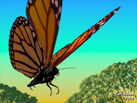
The Rest of
the Picture
The butterfly was
positioned as though coming in for a landing, with the
wings elevated 60 degrees. The plant models were
sprigs of Hemlock generated using XFrog and imported
into Carrara. The background was a Bi-gradient
applied to a simple backdrop using Carrara's scene
effects. Three lights were used and Global
Illumination was turned on to produce the render.
That covers it for this
time around. This project covered a lot of
territory and I learned a great deal from it.
Good luck with your model
and Happy
Rendering. |
|